The FACT design approach was created in 2005 by Jonathan Brigham Hopkins while a Master’s student in Professor Martin L. Culpepper’s Precision Compliant Systems Laboratory at MIT. FACT was first published in a short conference paper in the 2006 proceedings of the 21st Annual Meeting of the American Society for Precision Engineering[4] and was later published in depth in Hopkins’ 2007 Master's thesis.[5] FACT has been expanded in later works such as Hopkins' 2010 PhD Thesis.
Other compliant mechanism design methods include generative design, pseudo-rigid-body analysis,[6] and other constraint-based and [screw theory]-based design approaches.[7] See the main article for pros and cons of kinematics and structural optimization.
Fundamentals
FACT combines principles of screw theory, linear algebra, projective geometry, and exact-constraint design. The methodology employs a library of vector spaces derived from these principles and represented by geometric shapes. These shapes are categorized into freedom spaces, constraint spaces, and actuation spaces, each serving a unique purpose in the design process.
Freedom Spaces represent the allowed deformations of a system; the system's degrees of freedom (DOF). They are modeled as twist vectors.
Constraint Spaces guide the arrangement of flexible elements within a system to ensure it deforms only as intended. Each constraint space is complementary to a freedom space. They are modeled as wrench vectors.
Actuation Spaces guide the arrangement, number, and kind of actuators within a flexible system so that the system deforms as desired under load. Like constraint spaces, they are modeled as wrench vectors[8]
FACT synthesis
The FACT library allows traversal of the complete solution space of flexible systems for any combination of degrees of freedom. The rules of FACT vary depending on the configuration of the flexible system desired. Here are the basic steps to design a parallel flexure bearing.
Determine how the stage should move. What degrees of freedom (DOF) are needed? (Fig 1)
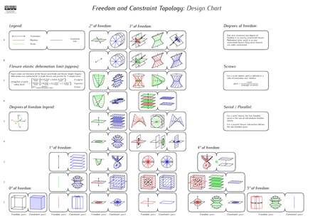
Find the matching freedom space in the FACT library (Fig 2)
Identify the constraint space matching the required freedom space (Fig 2)
Design the rigid bodies and connect each flexture to each body at their ends. When one body is held fixed, it becomes the "ground". The other body (the "stage") then attains the chosen DOF.
Sometimes it may be desireable to over-constrain the system by adding redundant constraints within the constraint space. This adds stiffness and may be required for symmetry, which can improve thermal stability.
Fig 1: A set of four degrees of freedom (three intersecting and orthogonal red rotation lines and one black translation arrow)Fig 2: The complementary freedom (red) and constraint (blue) spaces for the degrees of freedom shown in Fig 1 (4 DOF column, type 1 in the FACT library)Fig 3: Selecting wire flexure elements from within the example's constraint space such that the resulting topology is exactly-constrainedFig 4: Two parallel flexure systems with identical topology but different rigid body geometries. They each achieve the DOFs from Fig 1Recreation of FACT library of freedom and constraint spaces used to design parallel flexure systems, in PDF with additional information added
Limitations
All flexible systems can be organized according to three primary configurations – parallel, serial, and hybrid. FACT alone covers parallel, serial, and some hybrid systems.
Parallel systems[1][2][3] consist of two rigid bodies connected directly together by parallel flexible elements.
Serial systems[10][11] consist of two or more parallel systems stacked or nested in a chain from one rigid body to the next.
Hybrid systems[12] consist of any other configuration of parallel and serial system combinations.
Interconnected hybrid systems[13] are a special kind of hybrid configuration where intermediate rigid bodies are also interconnected together by flexible elements, which create internal loops within the system. FACT must be supplemented with Graph theory in order to handle such systems.[13]Mechanical metamaterials fall in this category.[14]
^Jensen, Brian D.; Howell, Larry L. (1 December 2003). "Identification of Compliant Pseudo-Rigid-Body Four-Link Mechanism Configurations Resulting in Bistable Behavior". Journal of Mechanical Design. 125 (4): 701–708. doi:10.1115/1.1625399.
^Li, Chenglin; Chen, Shih-Chi (1 May 2023). "Design of compliant mechanisms based on compliant building elements. Part I: Principles". Precision Engineering. 81: 207–220. doi:10.1016/j.precisioneng.2023.01.006.
^Maxwell, James Clerk; Nivens, W. D. (1890). General Considerations Concerning Scientific Apparatus in The Scientific Papers of James Clerk Maxwell. Dover Press.
_library_of_freedom_and_constraint_spaces_used_to_design_parallel_flexure_systems.jpg)
.jpg)

.jpg)