|
Hydraulic head
   Hydraulic head or piezometric head is a specific measurement of liquid pressure above a vertical datum.[1][2] It is usually measured as a liquid surface elevation, expressed in units of length, at the entrance (or bottom) of a piezometer. In an aquifer, it can be calculated from the depth to water in a piezometric well (a specialized water well), and given information of the piezometer's elevation and screen depth. Hydraulic head can similarly be measured in a column of water using a standpipe piezometer by measuring the height of the water surface in the tube relative to a common datum. The hydraulic head can be used to determine a hydraulic gradient between two or more points. DefinitionIn fluid dynamics, head is a concept that relates the energy in an incompressible fluid to the height of an equivalent static column of that fluid. From Bernoulli's principle, the total energy at a given point in a fluid is the kinetic energy associated with the speed of flow of the fluid, plus energy from static pressure in the fluid, plus energy from the height of the fluid relative to an arbitrary datum.[3] Head is expressed in units of distance such as meters or feet. The force per unit volume on a fluid in a gravitational field is equal to ρg where ρ is the density of the fluid, and g is the gravitational acceleration. On Earth, additional height of fresh water adds a static pressure of about 9.8 kPa per meter (0.098 bar/m) or 0.433 psi per foot of water column height. The static head of a pump is the maximum height (pressure) it can deliver. The capability of the pump at a certain RPM can be read from its Q-H curve (flow vs. height). Head is useful in specifying centrifugal pumps because their pumping characteristics tend to be independent of the fluid's density. There are generally four types of head:
ComponentsAfter free falling through a height in a vacuum from an initial velocity of 0, a mass will have reached a speed where is the acceleration due to gravity. Rearranged as a head: The term is called the velocity head, expressed as a length measurement. In a flowing fluid, it represents the energy of the fluid due to its bulk motion. The total hydraulic head of a fluid is composed of pressure head and elevation head.[1][2] The pressure head is the equivalent gauge pressure of a column of water at the base of the piezometer, and the elevation head is the relative potential energy in terms of an elevation. The head equation, a simplified form of the Bernoulli principle for incompressible fluids, can be expressed as: where
In an example with a 400 m deep piezometer, with an elevation of 1000 m, and a depth to water of 100 m: z = 600 m, ψ = 300 m, and h = 900 m. The pressure head can be expressed as: where is the gauge pressure (Force per unit area, often Pa or psi),
Fresh water headThe pressure head is dependent on the density of water, which can vary depending on both the temperature and chemical composition (salinity, in particular). This means that the hydraulic head calculation is dependent on the density of the water within the piezometer. If one or more hydraulic head measurements are to be compared, they need to be standardized, usually to their fresh water head, which can be calculated as: where
Hydraulic gradientThe hydraulic gradient is a vector gradient between two or more hydraulic head measurements over the length of the flow path. For groundwater, it is also called the Darcy slope, since it determines the quantity of a Darcy flux or discharge. It also has applications in open-channel flow where it is also known as stream gradient and can be used to determine whether a reach is gaining or losing energy. A dimensionless hydraulic gradient can be calculated between two points with known head values as: where
The hydraulic gradient can be expressed in vector notation, using the del operator. This requires a hydraulic head field, which can be practically obtained only from numerical models, such as MODFLOW for groundwater or standard step or HEC-RAS for open channels. In Cartesian coordinates, this can be expressed as: This vector describes the direction of the groundwater flow, where negative values indicate flow along the dimension, and zero indicates 'no flow'. As with any other example in physics, energy must flow from high to low, which is why the flow is in the negative gradient. This vector can be used in conjunction with Darcy's law and a tensor of hydraulic conductivity to determine the flux of water in three dimensions. In groundwater
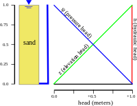
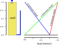
The distribution of hydraulic head through an aquifer determines where groundwater will flow. In a hydrostatic example (first figure), where the hydraulic head is constant, there is no flow. However, if there is a difference in hydraulic head from the top to bottom due to draining from the bottom (second figure), the water will flow downward, due to the difference in head, also called the hydraulic gradient. Atmospheric pressureEven though it is convention to use gauge pressure in the calculation of hydraulic head, it is more correct to use absolute pressure (gauge pressure + atmospheric pressure), since this is truly what drives groundwater flow. Often detailed observations of barometric pressure are not available at each well through time, so this is often disregarded (contributing to large errors at locations where hydraulic gradients are low or the angle between wells is acute.) The effects of changes in atmospheric pressure upon water levels observed in wells has been known for many years. The effect is a direct one, an increase in atmospheric pressure is an increase in load on the water in the aquifer, which increases the depth to water (lowers the water level elevation). Pascal first qualitatively observed these effects in the 17th century, and they were more rigorously described by the soil physicist Edgar Buckingham (working for the United States Department of Agriculture (USDA)) using air flow models in 1907. Head lossIn any real moving fluid, energy is dissipated due to friction; turbulence dissipates even more energy for high Reynolds number flows. This dissipation, called head loss, is divided into two main categories, "major losses" associated with energy loss per length of pipe, and "minor losses" associated with bends, fittings, valves, etc. The most common equation used to calculate major head losses is the Darcy–Weisbach equation. Older, more empirical approaches are the Hazen–Williams equation and the Prony equation. For relatively short pipe systems, with a relatively large number of bends and fittings, minor losses can easily exceed major losses. In design, minor losses are usually estimated from tables using coefficients or a simpler and less accurate reduction of minor losses to equivalent length of pipe, a method often used for shortcut calculations of pneumatic conveying lines pressure drop.[4] See also
Notes
References
|
Portal di Ensiklopedia Dunia


